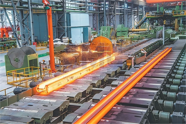
An electric arc furnace is an electric furnace that uses the high temperature generated by the electric arc between electrodes to smelt ores and metals.
When gas discharges to form an electric arc, the energy is highly concentrated, and the temperature in the arc zone is above 3000°C. Compared with other steelmaking furnaces, electric arc furnaces offer greater process flexibility for smelting metals, can effectively remove impurities such as sulfur and phosphorus, have easy temperature control, and occupy less space. They are suitable for the smelting of high-quality alloy steel.
Raw material for EAF
The raw materials for electric arc furnaces steelmaking mainly consist of solid scrap steel, alloy materials, pig iron for adjusting carbon content, and direct reduced iron or a portion of hot iron water can also be used. The range of raw material selection is broad; therefore, except for some ultra-low carbon special steel grades or those that must be processed with special methods such as vacuum treatment, or special alloy materials, most steel grades can be smelted.
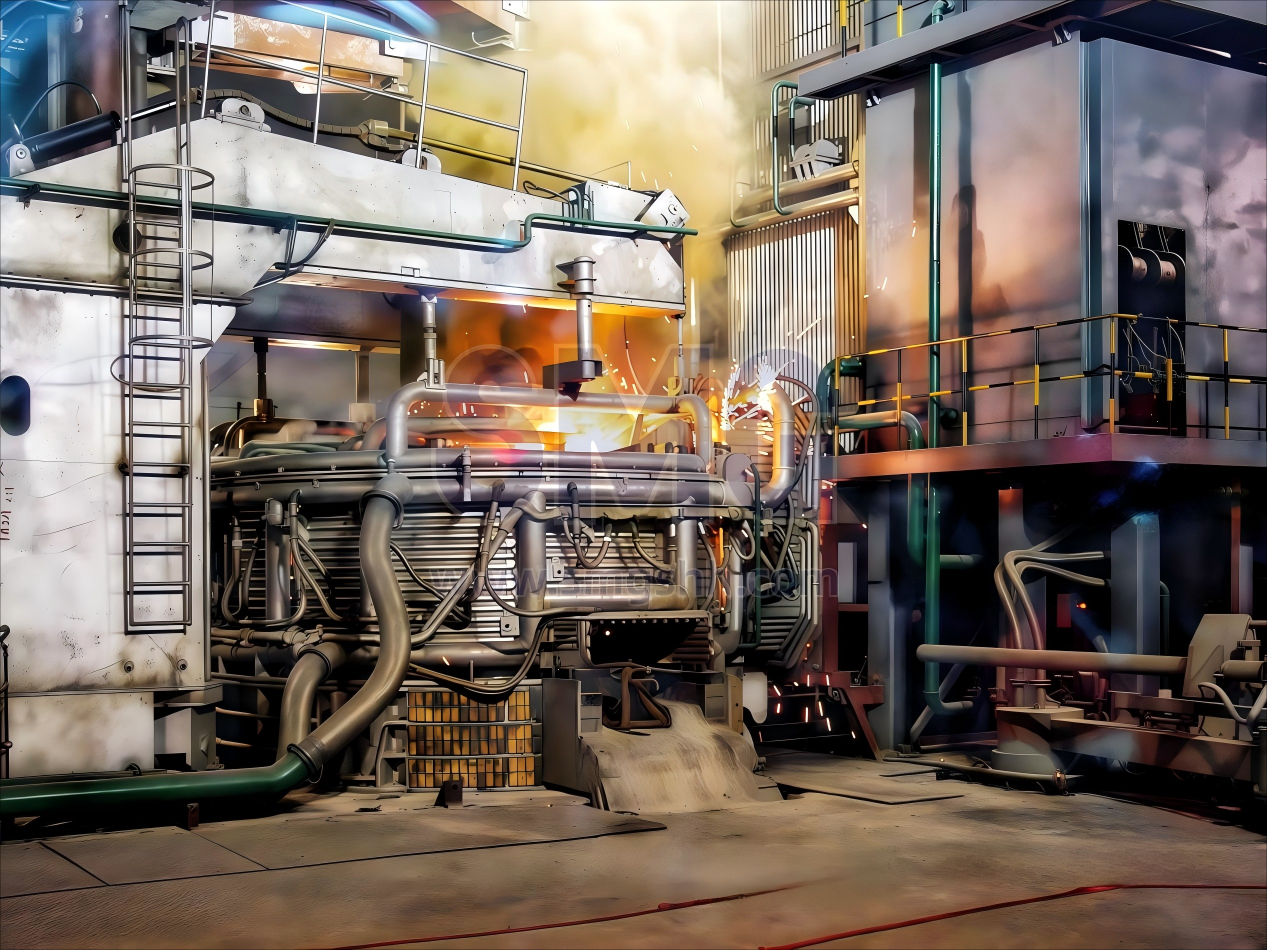
Working principle
The DC furnace supplies current to the furnace through a DC power supply. Current usually flows through the electrodes, forming an electric arc between them and the charge. The direct current between the electrode (usually made of graphite or copper) and the charge will cause the formation of an electric arc. An electric arc is a high-temperature plasma produced when current passes through a gas, with a temperature that can reach over 3000°C. The high temperature of the electric arc will rapidly heat and melt the metal waste inside the furnace. As each electrode inside the furnace can independently adjust the current, the operator can flexibly control the melting rate and energy distribution. Steelmaking electric furnaces usually operate in a reduced pressure or inert gas environment to minimize the influence of oxidation and impurities and ensure the quality of the molten metal. After the melting process is completed, the composition of the steel can be adjusted by adding alloying elements and chemical additives, and then refined to enhance the strength and toughness of the steel.
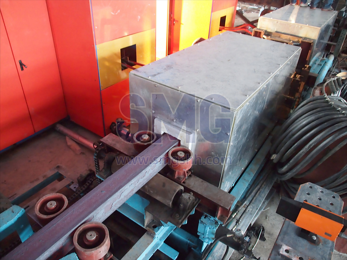
Mechanical structure of electric arc furnace
The electric arc furnace body consists of two main components: metal structures and furnace lining. The metal structures include various parts fabricated from metallic materials such as the furnace shell, furnace door, tapping mechanism, roof ring, and electrode sealing rings. The furnace lining refers to the refractory inner wall of the melting chamber, constructed with specialized heat-resistant materials to withstand the corrosive effects of high-temperature molten steel and slag.
Key mechanical systems of the electric arc furnace include: furnace tilting mechanism, electrode regulation system, and charging equipment. The furnace is equipped with a tilting mechanism to facilitate steel tapping and slag removal operations. During the smelting process, electrode lifting is controlled by an elevation system comprising: electrode holders, supporting columns, cross arms, and power transmission components;
Charging methods fall into two categories: door charging (manual operation, limited to small furnaces) and top charging (standard for most installations).
Based on positional adjustments during charging, systems are classified as: furnace body retractable type, roof rotating type and roof retractable type.
EAF Dust Collection:
Similar to oxygen converter steelmaking, the electric arc furnace steelmaking process generates significant amounts of dust and fumes, which must undergo dust collection treatment to meet environmental protection standards before being emitted.
Types of electric arc furnace
1.Indirect Arc Furnace
An alternating current electric arc furnace (AC EAF) generates an arc for smelting through alternating current conducted by graphite electrodes. As the current mainstream steelmaking furnace, the AC EAF features operational flexibility and wide applicability, capable of processing various scrap metal materials. With a relatively simple structure, this furnace type allows rapid start-stop operations, making it particularly suitable for small to medium-scale steel production needs.
2.Direct Arc Furnace (DC Arc Furnace)
A direct current electric arc furnace (DC EAF) produces an arc using direct current. Compared to AC furnaces, DC furnaces require fewer electrodes (typically only one graphite electrode), reducing operating costs while enhancing arc stability. Additionally, DC furnaces offer lower noise levels and greater potential for energy efficiency. However, their structural complexity is higher, and the initial investment cost is relatively greater.
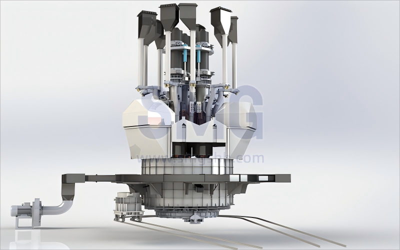
3.Submerged Arc Furnace
The submerged arc furnace (SAF) is a specialized electric furnace designed primarily for producing ferroalloys and other metals. Its electrodes are partially immersed in the charge material to create a reducing atmosphere suitable for metallurgical reduction reactions of ores such as manganese or chromium. Unlike conventional arc furnaces, the SAF is not used for steel smelting but rather for preparing alloy components with specific properties by precisely controlling high-temperature reaction environments (reaching up to 2000°C or higher). This furnace type can be customized according to the process requirements of different alloy products.
Electric arc furnace VS induction furnace
The choice between induction furnaces and electric arc furnaces depends on application-specific factors, including material type, product quality requirements, environmental impact, and operational efficiency.
Induction furnaces excel in energy efficiency, cleanliness, and precise temperature control, making them ideal for melting ferrous and non-ferrous alloys with minimal contamination. They are also more environmentally friendly, generating fewer emissions and less waste.
In contrast, electric arc furnaces are better suited for large-scale steel production and refining, particularly for high-quality steel grades, due to their superior metallurgical capabilities. However, they consume more energy and produce higher levels of waste, noise, and emissions.
Aspect
Electric furnace
Induction furnace
Working Principle
Uses electric arcs to generate heat for melting metal.
Uses electromagnetic induction to heat metal internally.
Metallurgical Function
Superior for large-scale production and refining high-purity steel grades.
Improved with IGBT technology; suitable for high-quality alloys and specialized steels.
Applications
Large-scale steel production, recycling scrap metal.
Small-scale operations, specialized steel production, high-quality alloys.
Advantages
High production capacity, excellent metallurgical control.
Energy-efficient, compact, precise temperature control.
Disadvantages
High energy consumption, significant capital investment, larger footprint.
Historically limited metallurgical capabilities, though improved with advancements.
Technological Advancements
N/A
IGBT technology enhances efficiency and metallurgical performance.